IoT - First Test of ESP8266 WiFi Module
Dec 30, 2014- Setup: This how-to was done using a Linux-PC (LMDE-Linux Mint Debian).
- Scope: first communication test with the module over wifi.
To try out the ESP8266 module I connected an USB-to-serial adapter which I ordered via the bay (“USB RS232 Serial TTL PL2303HX UART”).

It was possible to reconnect the 5V power supply from USB within the module (just opened it) to the 3.3 Volt needed for the module.

I wired up the module with the USB adapter; connected PIN CH_PD to VCC (3.3 Volt) and connected to PC. Red light goes on, blue flashes shortly.

| Label | Signal |
|---|---|
| VCC | 3.3V (max 3.6V) |
| GND | Ground |
| TXD | Transmit Data (3.3V) |
| RXD | Receive Data (3.3V) |
| CH_PD | Chip Power down: (LOW = Power down active) |
| GPIO0 | General Purpose I/O 0 |
| GPIO2 | General Purpose I/O 2 |
| RST | Reset (LOW = Reset active) |
 The picture is not the best - the yellow bounded cable connects CH_PD with VCC. The green connector from the USB-Serial-Converter goes to RXD, and the white to TXD.
After connecting the USB-Serial-Converter, my Linux shows following dmesg log:
[23081.471573] usb 1-3: New USB device found, idVendor=067b, idProduct=2303
[23081.471575] usb 1-3: New USB device strings: Mfr=1, Product=2, SerialNumber=0
[23081.471576] usb 1-3: Product: USB-Serial Controller
[23081.471577] usb 1-3: Manufacturer: Prolific Technology Inc.
[23081.471957] pl2303 1-3:1.0: pl2303 converter detected
[23081.472510] usb 1-3: pl2303 converter now attached to ttyUSB1
I installed GtkTerm via
sudo apt-get install gtkterm
I made sure the config file of gtkterm: “.gtktermrc” in my home folder contains the right config for my setup (in fact I needed to change the port and speed config):
[default]
port	= /dev/ttyUSB1
speed	= 115200
bits	= 8
stopbits	= 1
parity	= none
flow	= none
wait_delay	= 0
wait_char	= -1
rs485_rts_time_before_tx	= 30
rs485_rts_time_after_tx	= 30
echo	= False
crlfauto	= False
font	= "Nimbus Mono L, 14"
term_transparency	= False
term_show_cursor	= True
term_rows	= 80
term_columns	= 25
term_scrollback	= 200
term_visual_bell	= True
term_foreground_red	= 43253
term_foreground_blue	= 43253
term_foreground_green	= 43253
term_background_red	= 0
term_background_blue	= 0
term_background_green	= 0
term_background_saturation	= 0,500000
Now I was ready to play around with gtkterm. Actually my terminal was showing nothing, until I typed the first command (AT). For details about the below mentioned commandos (all starting with AT) - please visit: https://nurdspace.nl/ESP8266#AT_Commands or this website
AT

OK
AT+RST

OK

 ets Jan  8 2013,rst cause:4, boot mode:(3,7)

wdt reset
load 0x40100000, len 24444, room 16
tail 12
chksum 0xe0
ho 0 tail 12 room 4
load 0x3ffe8000, len 3168, room 12
tail 4
chksum 0x93
load 0x3ffe8c60, len 4956, room 4
tail 8
chksum 0xbd
csum 0xbd

ready

AT+GMR
00160901

OK
AT?
no this fun
AT+CWMODE?
+CWMODE:2

OK
AT+CWMODE=3

OK
AT+CWMODE?
+CWMODE:3

OK
AT+CWLAP
+CWLAP:(0,"",0)
+CWLAP:(4,"wifi1",-86)
+CWLAP:(3,"wifi2",-72)
+CWLAP:(3,"wifi3",-83)
+CWLAP:(3,"mywifi",-63)

OK
AT+CWJAP="mywifi","mypass"

OK
AT+CIFSR
192.168.1.20
After above commandos the module is connected with my home wifi (“mywifi”) which is secured with a password. The IP adress of the module is “192.168.1.20” (automatically received by the DHCP of the wifi router). Now I will start a TCP server listening on Port 8001 on the module (timeout is set to 180 sec because the module handles only a limited number of connections; we might free some long running idle ones):
OK
AT+CIPSERVER=1,8001

OK
AT+CIPSTO=180
On the linux box I open a terminal; started a telnet connection; entered the message “Helo” and pressed >enter<:
telnet 192.168.15.20 8001
Trying 192.168.15.20...
Connected to 192.168.15.20.
Escape character is '^]'.
Helo
In the serial monitor (gtkterm) I can see the terminal receiving the message:
Link

+IPD,0,6:Helo

OK
That’s it!
Next step is to have an arduino react/respond on tcp messages.
After consulting some forums in the internet I have read, that some additional preparation of the module is needed to talk with arduino (downgrade baudrate of the module). By the way - some alternative firmware exists for running LUA and/or even a webserver on the module using the GPIOs directly. But I want to talk to the Arduino Nano, so I need the following steps.
Clone the flash utility:
git clone https://github.com/themadinventor/esptool.git
Get the firmware esp8266.9.2.2.bin or here and unzip it to the folder of the esptool.
Now connect GPIO0 to low and restart the module (with GPIO0 to low it boots to flashable mode).
Trying to run the flash utility gave me an error (note that my serial converter sits on USB1, your setup might be different!):
./esptool.py -p /dev/ttyUSB1 write_flash 0x000000 v0.9.2.2\ AT\ Firmware.bin
Traceback (most recent call last):
  File "./esptool.py", line 22, in <module>
    import serial
ImportError: No module named serial
So I had to install the python serial modul via pip:
sudo pip install pyserial
Downloading/unpacking pyserial
  Downloading pyserial-2.7.tar.gz (122kB): 122kB downloaded
  Running setup.py egg_info for package pyserial

Installing collected packages: pyserial
  Running setup.py install for pyserial
    changing mode of build/scripts-2.7/miniterm.py from 644 to 755

    changing mode of /usr/local/bin/miniterm.py to 755
Successfully installed pyserial
Cleaning up...
After that I was able to flash the firmware:
 ./esptool.py -p /dev/ttyUSB1 write_flash 0x000000 v0.9.2.2\ AT\ Firmware.bin
Connecting...
Erasing flash...
Writing at 0x0007ef00... (100 %)

Leaving...
Now we have to change the baudrate for gtkterm (see above for the details) and restart gtkterm:
[default]
port	= /dev/ttyUSB1
speed	= 9600
bits	= 8
stopbits	= 1
parity	= none
...
One thing has changed for the communication with the module after the upgrade: after every command entered in gtkterm, not only Return has to be hit, but additionally Ctrl + J as well (CR+LF). So what do we get? Let’s change the baudrate to 57600:
AT

OK
AT+GMR
0018000902

OK
AT+CIOBAUD?
+CIOBAUD:9600

OK
AT+CIOBAUD=57600
BAUD->57600

OK
R
-> reconfigure & restart gtkterm!
As the new firmware changed some settings, we need to issue some more commands to get our tcp server back online (this time on ip 192.168.1.25….):
AT+CIPMUX?
+CIPMUX:0

OK
AT+CIPMUX=1

OK
AT+CIPMUX?

+CIPMUX:1

OK
AT+CIPSERVER=1,8001

OK
AT+CIFSR

192.168.4.1
192.168.1.25

OK
Link

+IPD,0,6:helo

OK
Now I will be ready to connect the Arduino Nano to my wifi module!
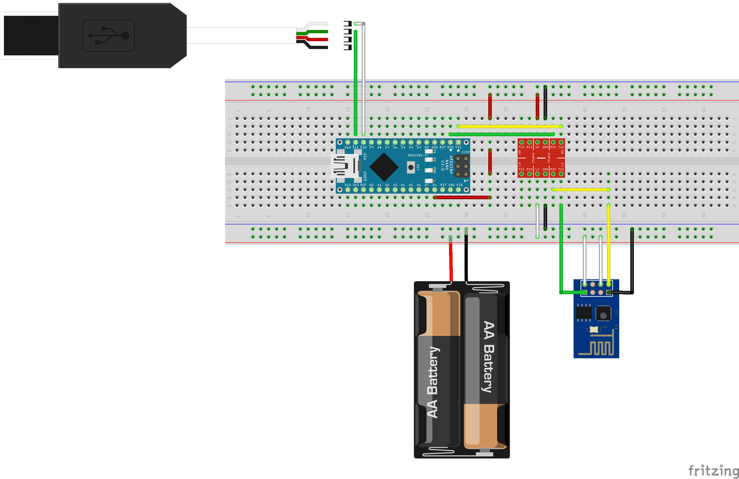
Connecting Arduino Nano is done really easily, with one level shifter (a resistor should work as well). I connected additionally the USB-Serial-Converter to the SoftSerial Arduino to see debug messages.
The Arduino is powered through the USB connection to the PC. During upload of the Arduino Sketch, the serial connection to the Wifi module has to be removed and reconnected afterwards.
I have pulled the CH_PD Pin to VCC, first with resistor (10k) then without. Without it was working more stable for me. Here the big picture:

What we now need is the corresponding Arduino Sketch. I will upload it soon to my GitHub repo - here the first draft, inspired by Ray Wang @ Rayshobby LLC
/* ====== ESP8266 TCP Demo ======
 * Receive & Respond via TCP
 * (Updated Dec 30, 2014)
 * ==========================
 *
 * Change SSID and PASS to match your WiFi settings.
 * The IP address is displayed to soft serial upon successful connection.
 *
 * Inspired by
 * Ray Wang @ Rayshobby LLC
 * http://rayshobby.net/?p=9734
 * http://raysfiles.com/arduino/ESP8266a_arduino.ino
 */

#include <SoftwareSerial.h>

#define BUFFER_SIZE 512
#define esp Serial
#define SSID  "mywifi"      // change this to match your WiFi SSID
#define PASS  "mypassword"     // change this to match your WiFi password
#define PORT  "8001"          // using port 8001 by default

char buffer[BUFFER_SIZE];

// Software Serial for debug
SoftwareSerial dbg(10,11);  // use pins 10, 11 for software serial

// By default we are looking for OK\r\n
char OKrn[] = "OK\r\n";

// LED Pin
const int LED = 13;


byte wait_for_esp_response(int timeout, char* term=OKrn) {
  unsigned long t=millis();
  bool found=false;
  int i=0;
  int len=strlen(term);
  // wait for at most timeout milliseconds
  // or if OK\r\n is found
  while(millis()<t+timeout) {
    if(esp.available()) {
      buffer[i++]=esp.read();
      if(i>=len) {
        if(strncmp(buffer+i-len, term, len)==0) {
          found=true;
          break;
        }
      }
    }
  }
  buffer[i]=0;
  dbg.print(buffer);
  return found;
}

void setup() {

  // assume esp8266 operates at 57600 baud rate
  // change if necessary to match your modules' baud rate
  esp.begin(57600);

  dbg.begin(9600);
  dbg.println("begin.");

  // Setup LED PIN as output
  pinMode(LED, OUTPUT);

  // blink test
  digitalWrite(LED, HIGH); // LED on
  delay(500); // 500 ms delay
  digitalWrite(LED, LOW); // LED off

  setupWiFi();

  // print device IP address
  dbg.print("device ip addr:");
  esp.println("AT+CIFSR");
  wait_for_esp_response(1000);
}

bool read_till_eol() {
  char incomingByte = 0;   // for incoming serial data
  static int i=0;
  if(esp.available()>0) {
    incomingByte = esp.read();
      buffer[i++]=incomingByte;
      if(i==BUFFER_SIZE)  i=0;
      if(i>1 && buffer[i-2]==13 && buffer[i-1]==10) {
        buffer[i]=0;
        i=0;
        dbg.print(buffer);
        return true;
    }
  }
  return false;
}

void loop() {
  int ch_id, packet_len;
  char *pb;
  if(read_till_eol()) {
    dbg.println("----------------------------------");
    if(strncmp(buffer, "+IPD,", 5)==0) {
      // request: +IPD,ch,len:data
      sscanf(buffer+5, "%d,%d", &ch_id, &packet_len);
      if (packet_len > 0) {
        // read serial until packet_len character received
        // start from :
        pb = buffer+5;
        while(*pb!=':') pb++;
        pb++;
        dbg.print("Message received: ");
        dbg.println(pb);
        send_Response(ch_id, "ACK");
        if (strncmp(pb, "LEDON", 5) == 0) {
          digitalWrite(LED, HIGH); // LED on
        }
        if (strncmp(pb, "LEDOFF", 6) == 0){
          digitalWrite(LED, LOW); // LED on
        }
      }
    }
  }
}


void send_Response(int ch_id, String content) {
  esp.print("AT+CIPSEND=");
  esp.print(ch_id);
  esp.print(",");
  esp.println(content.length());
  if(wait_for_esp_response(2000, "> ")) {
    esp.print(content);
  } else {
    esp.print("AT+CIPCLOSE=");
    esp.println(ch_id);
  }
}


void setupWiFi() {
  // try empty AT command
  esp.println("AT");
  wait_for_esp_response(1000);

  // set mode 1 (client)
  esp.println("AT+CWMODE=1");
  wait_for_esp_response(1000);

  // reset WiFi module
  esp.print("AT+RST\r\n");
  wait_for_esp_response(1500);

  // join AP
  esp.print("AT+CWJAP=\"");
  esp.print(SSID);
  esp.print("\",\"");
  esp.print(PASS);
  esp.println("\"");
  // this may take a while, so wait for 5 seconds
  wait_for_esp_response(5000);

  esp.println("AT+CIPSTO=30");
  wait_for_esp_response(1000);

  // start server
  esp.println("AT+CIPMUX=1");
  wait_for_esp_response(1000);

  esp.print("AT+CIPSERVER=1,"); // turn on TCP service
  esp.println(PORT);
  wait_for_esp_response(1000);


}
A little success: Arduino sends correctly the AT commands to connect to the network! It receives an IP adress, I even can telnet to it!
I can see (on the debug serial) following commands running through:
begin.
AT
OK
AT+CWMODE=1
no change
AT+RST
OK
AT+CWJAP="mywlan","mypassword"
B�
r�Ĥ���HB߬!{�����1�!�+!��B(�C)����B�B1�c+&ƅ��"�C�*�B����!(��9*)%�DŽ�b�c����Cx��B)�!���r�,%��D��c����C�!愆D
[System Ready, Vendor:www.ai-thinker.com]
AT+CIPSTO=30
ERROR
AT+CIPMUX=1
OK
AT+CIPSERVER=1,8080
OK
device ip addr:AT+CIFSR
192.168.1.30
OK
What does not work?
I wanted to switch the on-board LED of the Arduino via TCP commands (“LEDON” / “LEDOFF”) but at the moment I am struggling with the communication from the esp8266 to the Arduino. Sending the message “Hello” through a telnet terminal, I can see that the Wifi module is sending the complete message: “+IPD,0,7:Hello” but only a crippled message is received by the Arduino “+0lloOK”.
….to be continued….
If you run into problems or if you have any suggestions for the mistakes I have made, please leave a comment!